In this blog post I will explain how to calibrate your stereo camera which will help us in obtaining accurate depth information.
The original blogpost was created on Sept 2021 and migrated to the new website, thus the code may need to be revised.

This blog post is part of a 3 part series on detecting depth using a PS4 camera:
- Episode 1 - PS4 Camera on Windows
- Episode 2 - Camera Calibration
- Episode 3 - Depth Estimation
Throughout the rest of the tutorial, you will gain experience in using OpenCV and Python to handle image streams, combine stereo images to obtain depth information, running Pose Estimation models to extract skeletons from frames and how to transform 2D skeletons into 3D skeletons for animations.
👉 Get the latest version of the code here
Stereo cameras and how to get one
Fun fact
The same way sound can be mono or stereo cameras can also be stereo by having two or more lenses which can view a scene from different angles.
Stupid question: Why aren’t there so many one eyed pirates?
Stupid answer: Because they can get more information (e.g. how far things are) by having two eyes. And because not so many got stabbed in the eye.
That’s the same reason for which many companies choose to use stereo cameras for self-driving cars, because they haven’t got stabbed in the (mobile) eye yet.
Bad jokes aside, companies use stereo cameras for driving support such as for automatic braking and white line recognition, using the distance between vehicles in front and acquired images (source) or gaming (e.g. the PS4 camera).
Why we need to calibrate?
Since cameras come in all shapes and sizes, there is no one solution fits all when we want to obtain depth information.
For instance, one of the steps in obtaining depth information is that we will need to match the pixels of the left camera with the pixels of the right camera. If the image is distorted in either one of the cameras, the matching algorithm is going to have a hard time and will produce bad results.
In other words, we calibrate the camera in order to:
find out what are the intrinsic parameters of the camera (optical center and focal length) and fix possible distortions
find out what are the extrinsic parameters of the camera (distance between cameras and camera rotations) such that the disparity maps that we produce are accurate.

TDS - The Pinhole Camera Model
In this blog post we will only focus on the steps and code which are needed for obtaining the intrinsic parameters.
If you would like to know more about the theory behind, I’ve added a few sources at the references of the blog post.
Prerequisites
Before we get our hands dirty and get into the code, we will have to make sure that we have everything needed and don’t stop midway questioning our existence.
Print the calibration pattern
In order to calibrate the camera, we will need to use a calibration pattern which we will use to check if the camera sees it the same way as we do, and if not force it to (like in any healthy relationship).
Install requirements.txt
In order to version the libraries which are being used and make sure that we both have the same result, I created a requirements.txt which contains all the libraries you will need to install.
To install them, you will need to open a terminal, navigate to the location of requirements.txt and run the following command:
Aaaand … if you don’t want to be a barbarian and ruin the versions of your already installed libraries, you may want to also create a virtual environment before that:
python -m pip install virtualenv # install virtualenv
python -m venv .env              # create an environment named .env
.env/Source/activate             # activate the environment
pip install -r requirements.txt  # install the requirements
Warning
We’ll be using the PS4DataSource class that I’ve created based on the previous blog post and which can be downloaded from the GitHub repo.
If you don’t have a PS4 camera, you will have to derive the class and make it work for your use case.
Gathering calibration data
First, let’s get the constants straight because we will be using them for collecting calibration data.
self.display_font = cv2.FONT_HERSHEY_SIMPLEX # Cowntdown timer font
self.camera_index = 0  # Which camera to use for calibration
self.total_photos = 30 # Number of images to take
self.cnt_interval = 5  # Interval for count-down timer, seconds

self.counter = 0 # How many frames were captured so far

self.data_source = PS4DataSource(self.camera_index) # Create capture source
After that, we will be reading frames two at a time (one for each lens) and save them in the destination folder.
# Set folder where to save the frames
frame_path = './data/calibration/pairs'

# Record start time
start = time.time()
for frame_r, frame_l in self.data_source.stream():
    if frame_r is None or frame_l is None:
        break

    # How much time has passed from start
    cntdwn_timer = int(time.time() - start)

    # If cowntdown is zero - let's record next image
    if cntdwn_timer >= self.cnt_interval:
        self.counter += 1

        # Save the frames
        frame_name = f'{dst_folder}/right_{self.counter}.png'
        cv2.imwrite(frame_name, frame_r)

        frame_name = f'{dst_folder}/left_{self.counter}.png'
        cv2.imwrite(frame_name, frame_l)

        # Display text and wait for person to asimilate
        print (f'Frame captured [{self.counter} of {self.total_photos}] ')
        time.sleep(1)

        # Record new start time
        start = time.time()

    # Stop recording if all images were recorded
    if self.counter >= self.total_photos:
        break

# Close the stream
self.data_source.close_stream()
Warning
It is very important that your calibration pattern is as flat as possible when recording the data. If there is any distortion in the surface of the pattern, that will propagate through the algorithm and produce inaccurate calibration parameters.
Obtaining camera parameters
Here we define the information which describes the calibration pattern and create a instance of the StereoCalibrator class.
# Where the frames were saved at
frame_path = './data/calibration/pairs'

# Calibration image information
calib_rows = 6
calib_columns = 9
calib_square_size = 2.5

# Create a instance of the stereo calibrator
frame_width, frame_height = self.data_source.get_frame_shape()
calibrator = StereoCalibrator(calib_rows,
                              calib_columns,
                              calib_square_size,
                              (frame_width, frame_height))
After which we iterate trough our saved frames and detect the corners of the calibration pattern. By comparing the corners of different frames from different angles and positions, the class is able to identify the intrinsic parameters of our camera and record them.
# Add calibration patter corners for each saved frame
for frame_r_path in Path(frame_path).glob('right_*.png'):
    frame_idx = frame_r_path.stem.split('_')[-1]

    frame_r_path = str(frame_r_path)
    frame_l_path = frame_r_path.replace('right', 'left')

    frame_r = cv2.imread(frame_r_path,1)
    frame_l = cv2.imread(frame_l_path,1)

    try:
        calibrator._get_corners(frame_r)
        calibrator._get_corners(frame_l)
    except ChessboardNotFoundError as error:
        print (error)
        print ("Pair No "+ str(frame_idx) + " ignored")
    else:
        calibrator.add_corners((frame_r, frame_l), True)
We then create a copy of the intrinsic parameters, such that we don’t have to run the calibration every time we wish to use the camera.
# Export calculated calibration information
print ('Starting calibration... It can take several minutes!')
calibration = calibrator.calibrate_cameras()
calibration.export('calibration_params')
print ('Calibration complete!')
And we also validate that the calibration is done correctly by rectifying a frame and looking for possible distortions.
# Lets rectify and show last pair after calibration
calibration = StereoCalibration(input_folder='calibration_params')
rectified_pair = calibration.rectify((frame_r, frame_l))
We can eyeball whether the image has distortions by choosing a landmark in the two frames (e.g. the sofa pillow) and see whether the red lines fall in the same place. In this case we can see that the pillow is a bit lower in the right frame than in the left one.
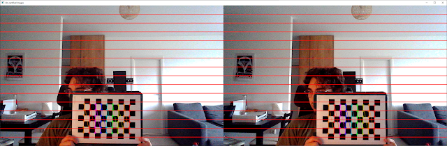
Visualizing uncalibrated frames
If we were to apply the correction on the frames, we see some black areas due to warping. The higher the black area, the more correction was done to the images.
Also if we were to look again at the pillow position, we see that the lines are positioned in the same respective place.
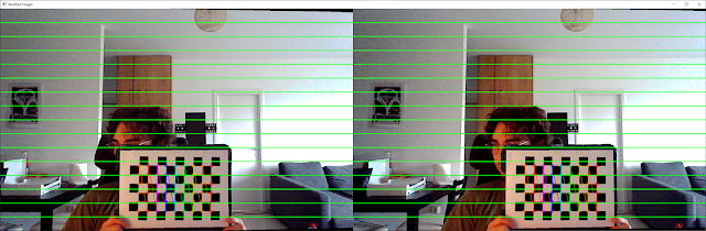
Visualizing calibrated frames
👉 Get the latest version of the code here
Summary
In today’s post we looked over:
- Why we need to calibrate stereo cameras
- How to collect data for calibration
- What are the scripts that we need to run for identifying intrinsic parameters
- How to load the parameters in order to rectify camera feed
This will be the building block for the next blog post where we will obtain disparity maps and visualize depth of objects in an image.
If you have any questions leave them in the comments and I’ll try to answer them as soon as I can.
Hope you enjoyed the blog post :)
Peace 🐐
References
J. Redmon (aka the dude that built YOLO) - 3D, Depth Perception, and Stereo
Stereopi (aka the basis for my code) - Depth Map on StereoPi tutorial
OpenCV docs (aka the CV Holy Bible) - OpenCV camera calibration